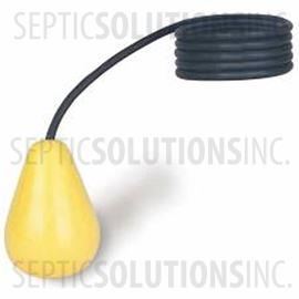
Pond Float Switch Wiring Diagram

For example water level controls is a float switch manufacturer that is revolutionizing the way float switches are used for water level sensing.
Pond float switch wiring diagram. A wiring diagram is a simplified standard photographic representation of an electric circuit. Let s start with the most basic float switch. Collection of float level switch wiring diagram. Float switch connection single phase water pump what is float switch.
Water level control s new float switches work by using probes instead of floats to detect or sense. Hello friends in this video i. Float switch is a type of level sensor a device used to detect the level of liquid with. Sump and sewage float switches have a float that raises and lowers depending on the water level in the sump basin to automatically control switch operation.
Float switches of the 21st century have come much further in the amount of operations your float switch can perform. Today i am hear to write about submersible pump control box wiring diagram in this post you will complete understood about 3 wire submersible pump wiring diagram which is an single phase submersible pump motor. When water rises to a preset level in the sump basin the switch turns on and the pump starts. When the water is drained down the switch turns off and the pump stops.
In this article we will discuss the correct way to hard wire a float switch to a submersible pump in order to achieve automatic operation. It reveals the parts of the circuit as simplified forms as well as the power and signal links in between the tools. To switch on 240vac pumps you would need a relay with two sets of contacts such as automation direct part number ad pr40 2a 120a. Submersible pumps use float switches to perform automatic operation.
A two wire single pole single throw float switch the rising action of the float can either close i e turn on a normally open circuit or it can open turn off a normally closed circuit installation scenarios might include a normally open float switch turning on a pump to empty a tank control schematic 2 or a normally closed. In this video how to use float switch wiring single phase on off motor using float switch diagram installation for water tank. This relay s coil is also rated at 120vac so our water level control can switch it on off at rated voltage. Why we called a single phase submersible motor a 3 wire submersible that we also know that we have two wire in single phase power supply.


